5. DMX-Address
Every DMX enabled fixture has to have some sort of address setting implemented into them.

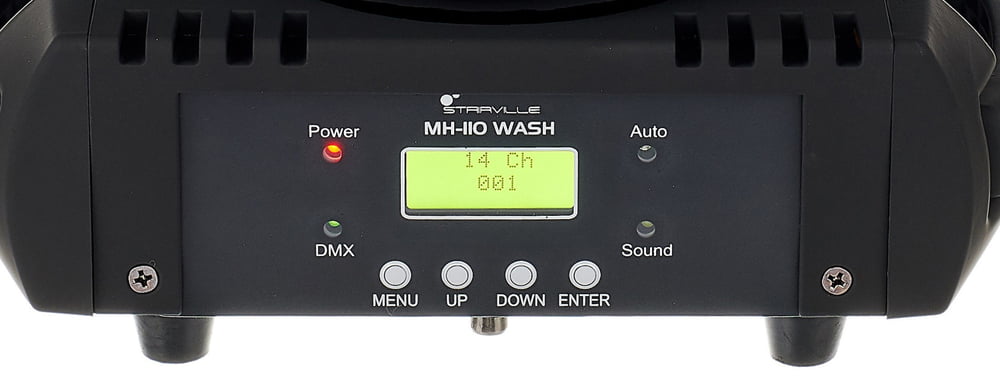
Panel from Stairville MH-110 Wash
Nowadays it’s common to have a built-in display on which the user navigates through a menu structure.

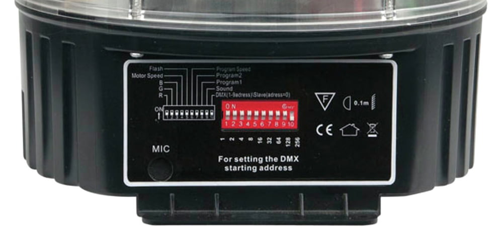
Panel from Showtec Disco Star 3x 3 Watt RGB Ball
Nevertheless in the earlier days it the so called „DIP- Switch“ was widely used. Basically being an array of tiny toggle switches, it allowed the technician to set the DMX address in binary count.
The assignment of the DIP switch is usually as in the following table:
| Switch | 1 | 2 | 3 | 4 | 5 | 6 | 7 | 8 | 9 | 10 |
| DMX-Adress | 1 | 2 | 4 | 8 | 16 | 32 | 64 | 128 | 256 | 512 |
If you flick switch number 5 in the on position, it will result in start address 16. Let’s imagine you would like to set the address to 20, you would need to combine the switches 3 + 5 (representing 4 + 16). It is always important to be informed about how many channels a specific fixture will take up. This information can be obtained in the user manual. The DMX chart lists all the available functions and their corresponding DMX values.
Example:
A Device takes 5 DMX-channels and is set to gather information starting at channel 20. The Device will react to the channels 20, 21, 22, 23 and 24 – 5 channels.
DMX Software
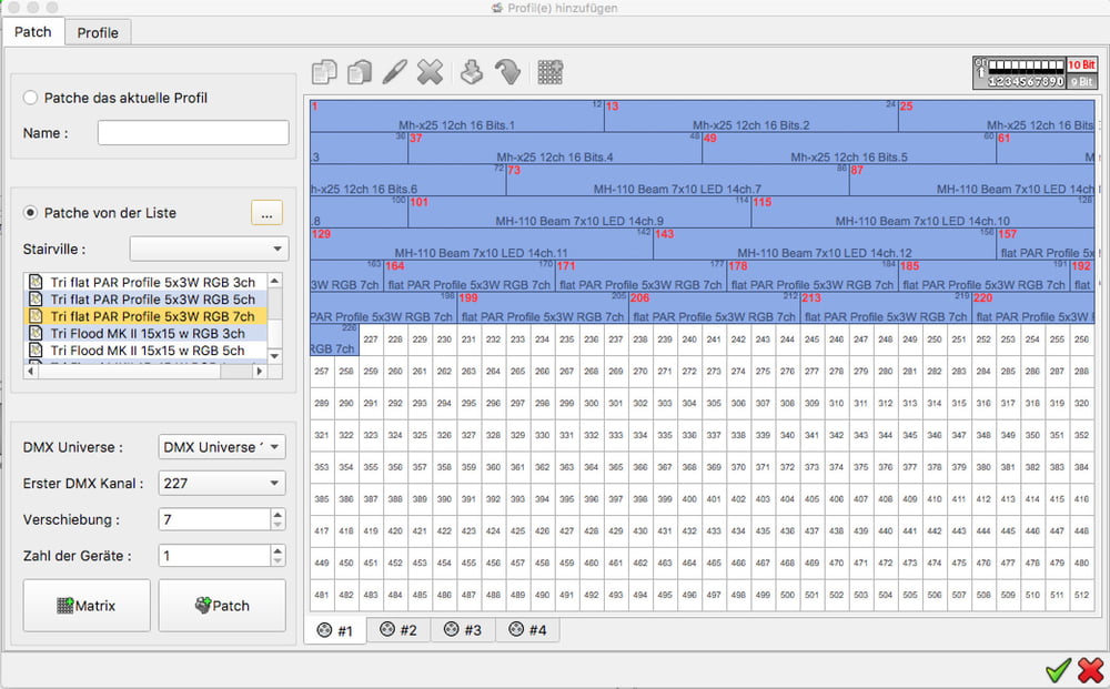
Software based light controllers like the Stairville DMX Joker visualize the occupation of a DMX Universe and help you to keep your patch in order.

Stairville DMX Joker software – patch window


